Rapid prototyping is the automatic construction of physical objects using additive manufacturing technology. The first techniques for rapid prototyping became available in the late 1980s and were used to produce models and prototype parts. Today, they are used for a much wider range of applications and are even used to manufacture production-quality parts in relatively small numbers. Some sculptors use the technology to produce complex shapes for fine arts exhibitions.
Prototyping technologies
1. Selective laser sintering (SLS)
2. Direct Metal Laser Sintering (DMLS)
3. Fused deposition modeling (FDM)
4. Stereolithography (SLA)
5. Laminated object manufacturing (LOM)
6. Electron beam melting (EBM)
7. 3D printing (3DP)
SELECTIVE LASER SINTERING (SLS)
(Thermoplastics, metals powders)
Sintering is a method for making objects from powder, by heating the material (below its melting point) until its particles adhere to each other
Direct Metal Laser Sintering (DMLS)
(Almost any alloy metal)
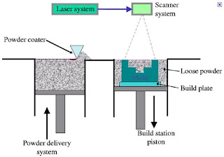
The DMLS process can be performed by two different methods, powder deposition and powder bed, which differ in the way each layer of powder is applied. In the powder deposition method, the metal powder is contained in a hopper that melts the powder and deposits a thin layer onto the build platform. In the powder bed method (shown below), the powder dispenser piston raises the powder supply and then a recoater arm distributes a layer of powder onto the powder bed. A laser then sinters the layer of powder metal. In both methods, after a layer is built the build piston lowers the build platform and the next layer of powder is applied. The powder deposition method offers the advantage of using more than one material, each in its own hopper. The powder bed method is limited to only one material but offers faster build speeds.
Fused deposition modeling (FDM)
(Thermoplastics, eutectic metals.)
In this process, a plastic or wax material is extruded through a nozzle that traces the part's cross sectional geometry layer by layer. The build material is usually supplied in filament form, but some setups utilize plastic pellets fed from a hopper instead. The nozzle contains resistive heaters that keep the plastic at a temperature just above its melting point so that it flows easily through the nozzle and forms the layer. The plastic hardens immediately after flowing from the nozzle and bonds to the layer below. Once a layer is built, the platform lowers, and the extrusion nozzle deposits another layer. The layer thickness and vertical dimensional accuracy is determined by the extruder die diameter, which ranges from 0.013 to 0.005 inches. In the X-Y plane, 0.001 inch resolution is achievable. A range of materials are available including ABS, polyamide, polycarbonate, polyethylene, polypropylene, and investment casting wax.
Stereolithography (SLA)
(photopolymer)Laminated object manufacturing(LOM)
(paper)
The first commercial Laminated Object Manufacturing (LOM) system was shipped in 1991. LOM was developed by Helisys of Torrance, CA. The main components of the system are a feed mechanism that advances a sheet over a build platform, a heated roller to apply pressure to bond the sheet to the layer below, and a laser to cut the outline of the part in each sheet layer. Parts are produced by stacking, bonding, and cutting layers of adhesive-coated sheet material on top of the previous one. A laser cuts the outline of the part into each layer. After each cut is completed, the platform lowers by a depth equal to the sheet thickness (typically 0.002-0.020 in), and another sheet is advanced on top of the previously deposited layers. The platform then rises slightly and the heated roller applies pressure to bond the new layer. The laser cuts the outline and the process is repeated until the part is completed. After a layer is cut, the extra material remains in place to support the part during build.
3D printing
(various materials)
3D printing
(various materials)
The process is similar to the Selective Laser Sintering (SLS) process, but instead of using a laser to sinter the material, an ink-jet printing head deposits a liquid adhesive that binds the material. Material options, which include metal or ceramic powders, are somewhat limited but are inexpensive relative to other additive processes. 3D Printing offers the advantage of fast build speeds, typically 2-4 layers per minute. However, the accuracy, surface finish, and part strength are not quite as good as some other additive processes. 3D Printing is typically used for the rapid prototyping of conceptual models (limited functional testing is possible).
The 3D printing process begins with the powder supply being raised by a piston and a leveling roller distributing a thin layer of powder to the top of the build chamber. A multi-channel ink-jet print head then deposits a liquid adhesive to targeted regions of the powder bed. These regions of powder are bonded together by the adhesive and form one layer of the part. The remaining free standing powder supports the part during the build. After a layer is built, the build platform is lowered and a new layer of powder added, leveled, and the printing repeated. After the part is completed, the loose supporting powder can be brushed away and the part removed. 3D printed parts are typically infiltrated with a sealant to improve strength and surface finish.
The 3D printing process begins with the powder supply being raised by a piston and a leveling roller distributing a thin layer of powder to the top of the build chamber. A multi-channel ink-jet print head then deposits a liquid adhesive to targeted regions of the powder bed. These regions of powder are bonded together by the adhesive and form one layer of the part. The remaining free standing powder supports the part during the build. After a layer is built, the build platform is lowered and a new layer of powder added, leveled, and the printing repeated. After the part is completed, the loose supporting powder can be brushed away and the part removed. 3D printed parts are typically infiltrated with a sealant to improve strength and surface finish.


